Tanzu vSphere 7 with Kubernetes on NSX-T 3.0 VDS Install Part 3: NSX-T Edges, Segments, Tier-0 Routing
In this section, we will configure NSX-T such as setting up the Transport Nodes, Edge VMs, configure Layer 2 Segments, Tier-0 uplinks and the routing required in preparation for vSphere with Kubernetes.
Step 0 – Prerequisite, as this guide is broken down into multiple sections and this section is mostly focus on the NSX-T Manager, it would be good to ensure that the following are configured. This will prevent switching back and forth between vCenter and NSX-T Manager. In customer or production environment, it would also likely to have different teams managing different things, such as Systems / VI admins managing vCenter and Network team will be managing NSX-T. Therefore, sometimes its hard to get both teams to be online at the same time, and thus, would be good to be clear on who needs to be configure what.
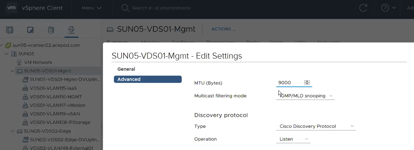
1) VDS is created and MTU size has been increased to 1600 or more than 1600. MTU 9000 is recommended. This MTU size has to match the size port configuration.
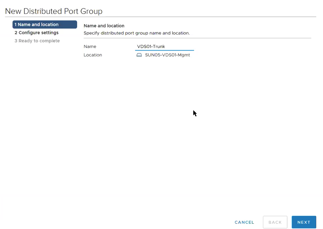
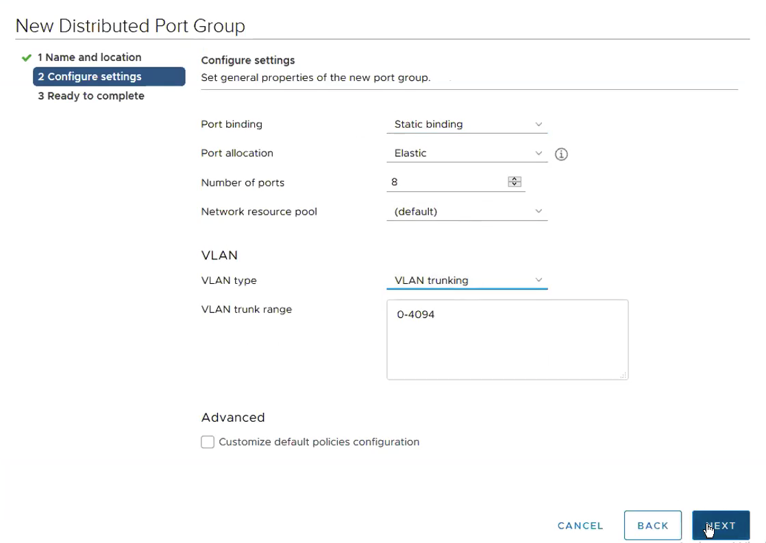
2) Portgroups that are going to be used for Edge VMs are created. This is where it gets tricky. Depending on the switch port configuration, you either create a portgroup with VLAN ID tagged or Trunk. This portgroup VLAN tag or no-tag or trunk has to match the switch port configuration. Trunk configuration is recommended. In my installation, since I’m going to validate one Physical NIC set up, the switch port configuration has to be Trunk.
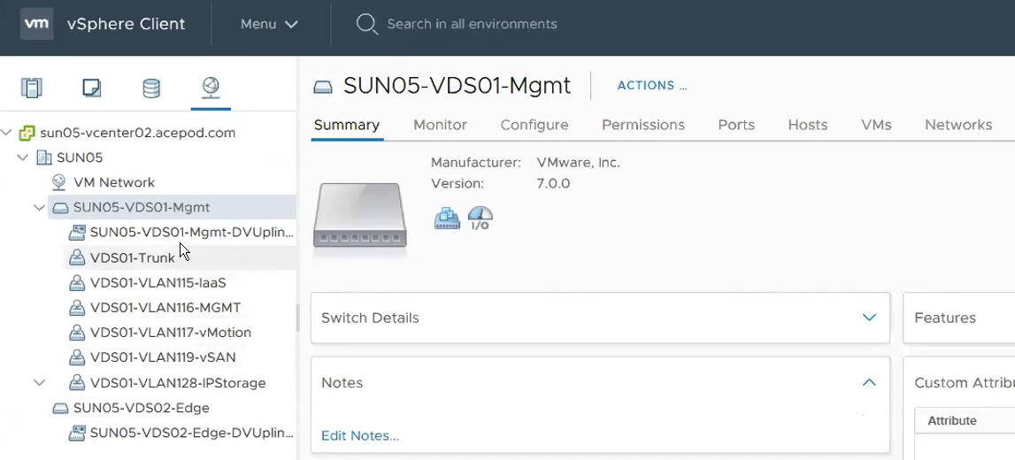
This shows the required relevant portgroups are configured.
— Network Team —
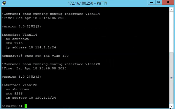
1) Ensure the switch is configured with the right MTU as well as the routing are configured. As you can see, the following is showing VLAN116 and VLAN120, these two VLANs are use for Geneve Overlay TEP.
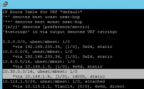
2) Uplink VLAN with Static Route being configured for Ingress / Egress Subnet.
Step 1 – Add License to NSX-T Manager.
Logging in to NSX-T manager.

System -> Licenses under Settings -> ADD
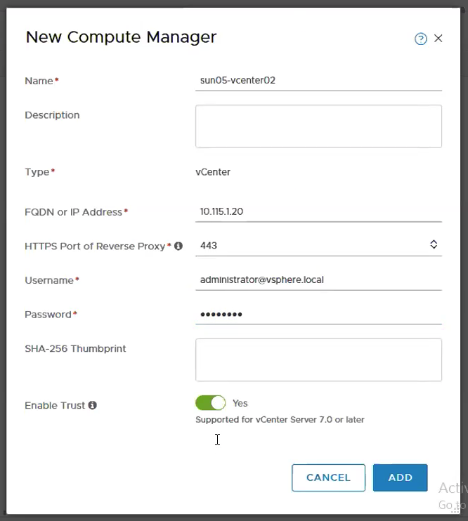
Step 2 – Add vCenter as Compute Manager.
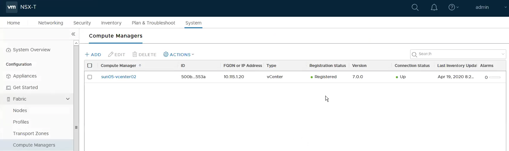
Start by adding the vCenter as Compute Manager. System -> Fabric -> Compute Managers
This shows that the Compute Manager is added successfully.
Step 3 – Create Uplink Profiles for ESXi Transport Nodes.
System -> Fabric -> Profiles -> Add
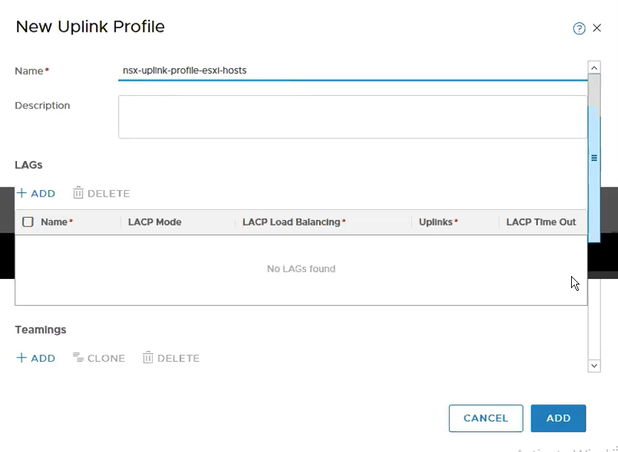
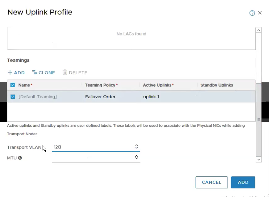
Configure Teaming & Active Uplinks and Transport VLAN.
Step 4 – Create Uplink Profiles for Edge VMs Transport Nodes.
System -> Fabric -> Profiles -> Add
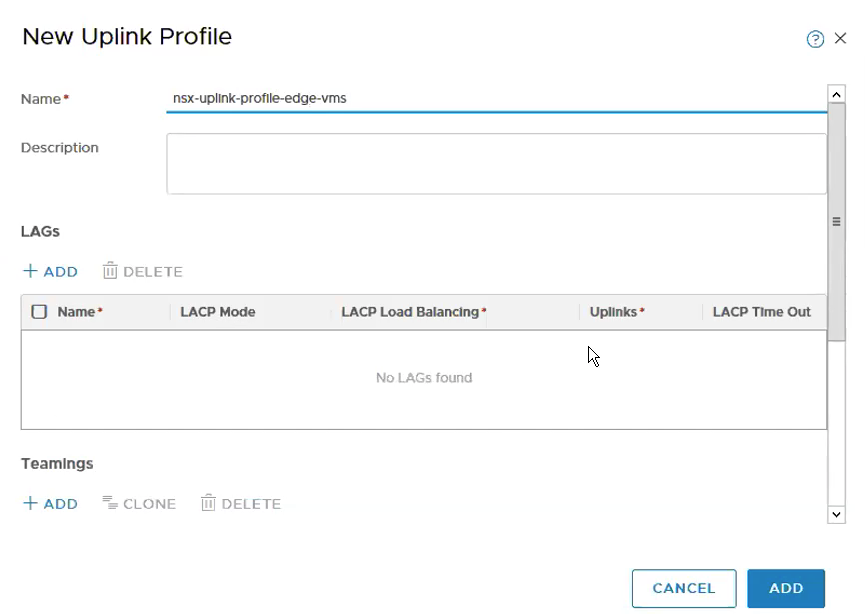
Configure Teaming & Active Uplinks, Transport VLAN and MTU.
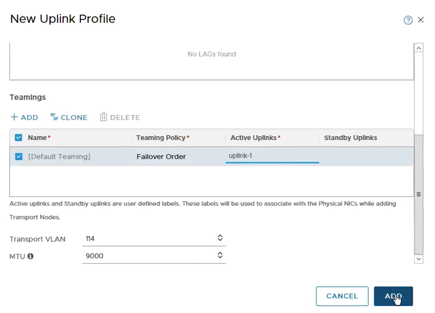
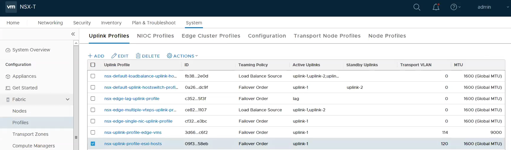
It will look like the following with the 2 new uplink profiles being created successfully.
Step 5 – Add IP Pools. As my Edge VMs are running in the same cluster as the Compute Cluster, I use a two VLANs approach to workaround. **You can read more on the this topic in the first part of the blog. Therefore, instead of one IP pools for TEPs, there will be a need for two IP Pools.
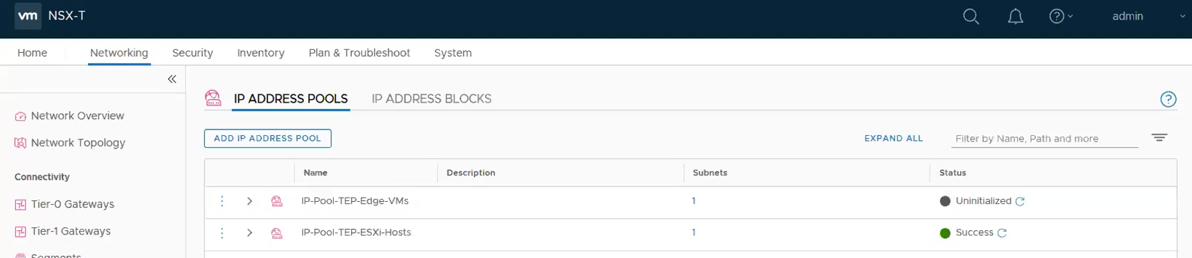
Networking -> IP Address Pools -> Add IP Address Pool
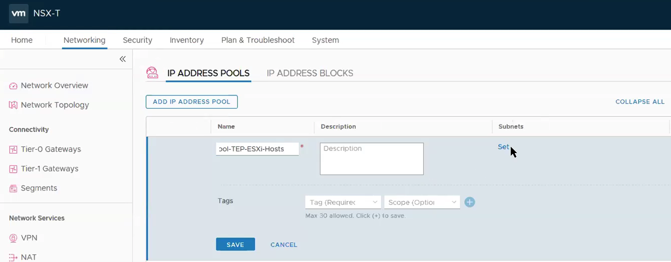
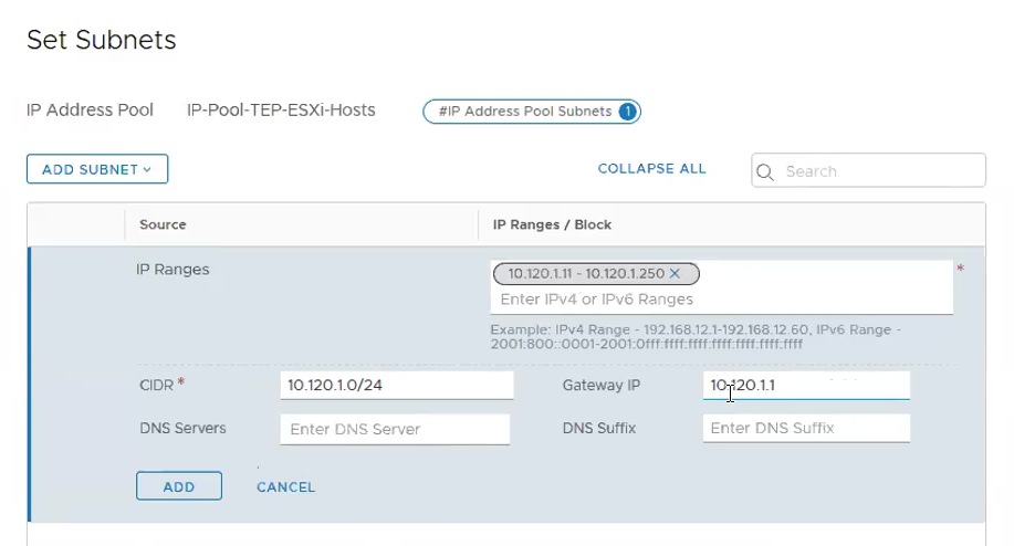
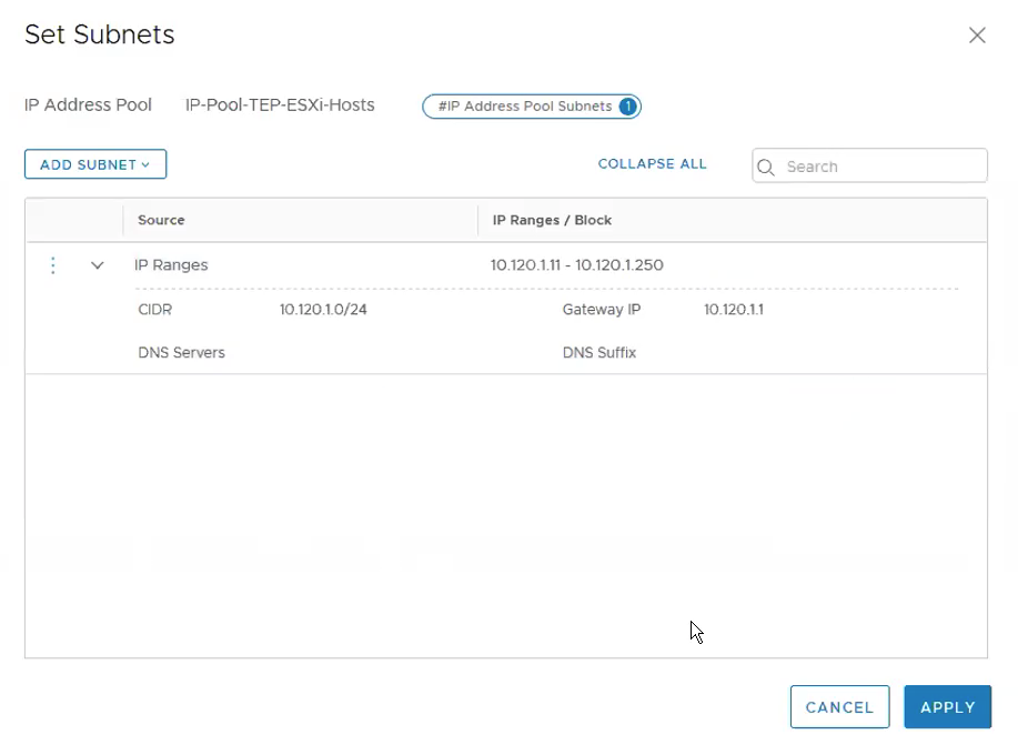
Under Subnets, Click on Set. **Ensure the Gateway IP is being configured as we require routing between the ESXi hosts TEP overlay network and the Edge TEP overlay network. Click ADD.
Click Apply.
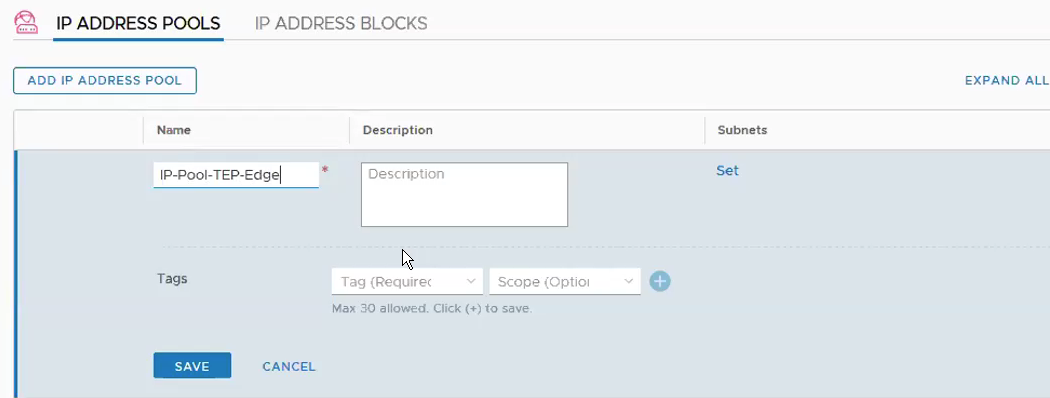
Add IP Pool for Edge VMs. Networking -> IP Address Pools -> Add IP Address Pool
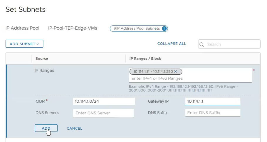
**Ensure the Gateway IP is being configured as we require routing between the Edge TEP overlay network and the ESXi hosts TEP overlay network. Click Add.
Click Apply.
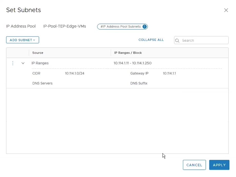
This is how it looks like once the two IP Pools for the TEPs are configured.
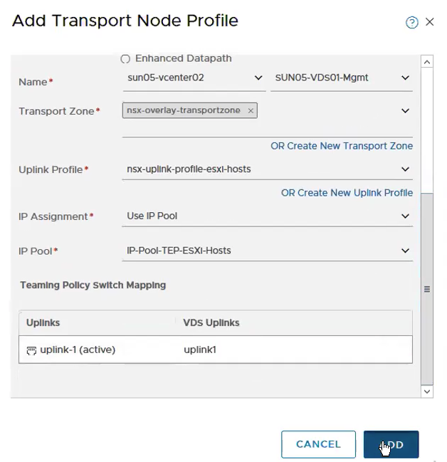
Step 6 – Create Transport Nodes Profiles for ESXi Hosts.
System -> Fabric -> Transport Node Profiles -> Add
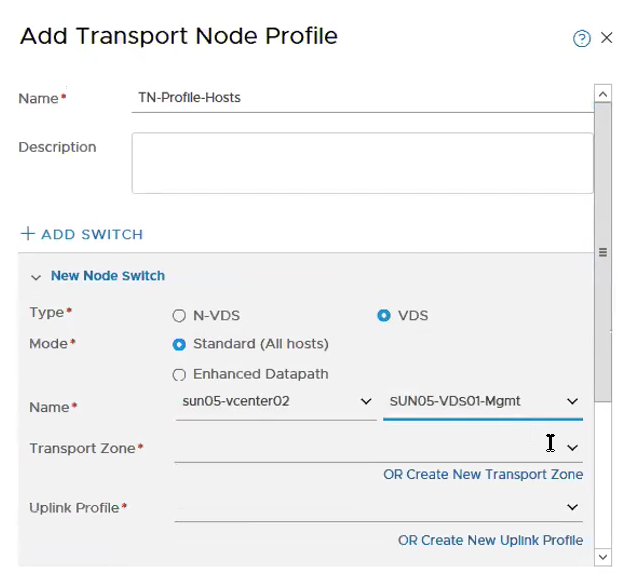
Configure Transport Zone, Uplink Profile.
Step 7 – Enabling NSX ESXi as Transport Nodes
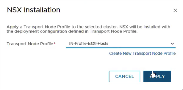
System -> Fabric -> Nodes -> Host Transport Nodes. Select the Computer Cluster and then Configure NSX.
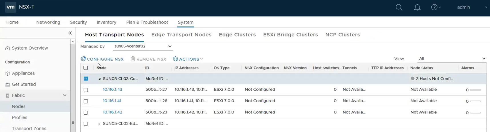
Select the Transport Node Profile we created at Step 6.
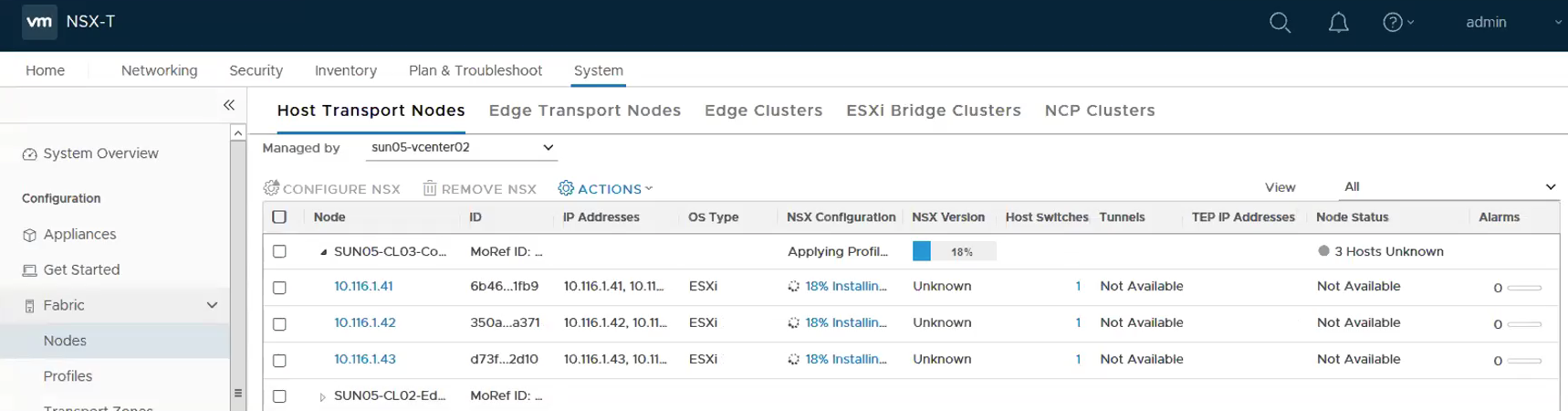
The following shows the installation is progressing.
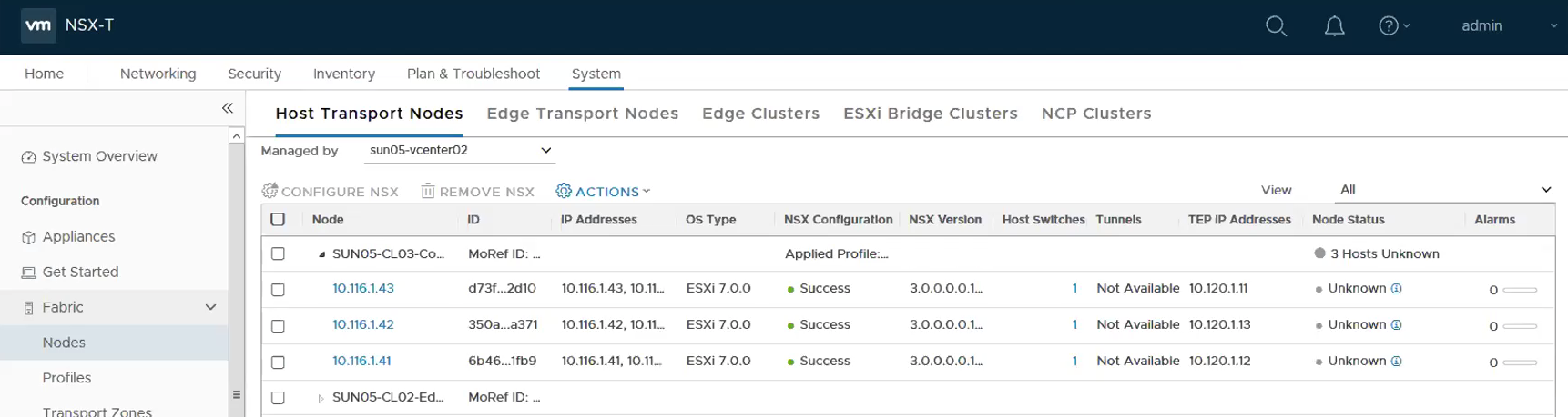
This show the following the hosts are successfully installed with NSX.
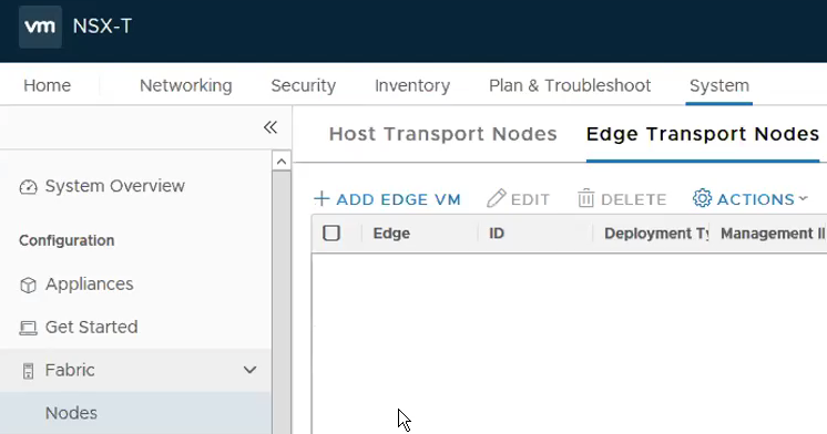
Step 8 – Deploying Edges
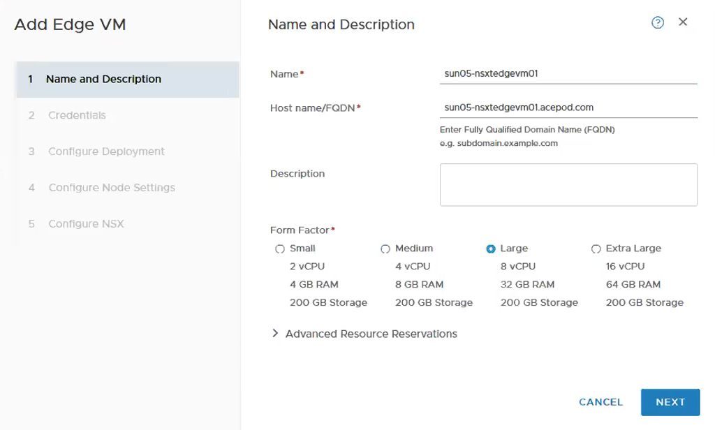
System -> Fabric -> Nodes -> Edge Transport Nodes. Click on ADD Edge VM.
Fill in the name, host name and choose the size. For vSphere with Kubernetes, you will need to deploy a minimum of Large Edge VM appliance.
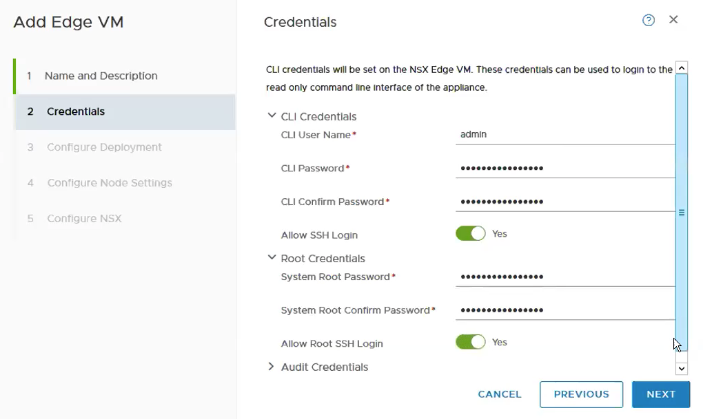
Fill in the credentials.
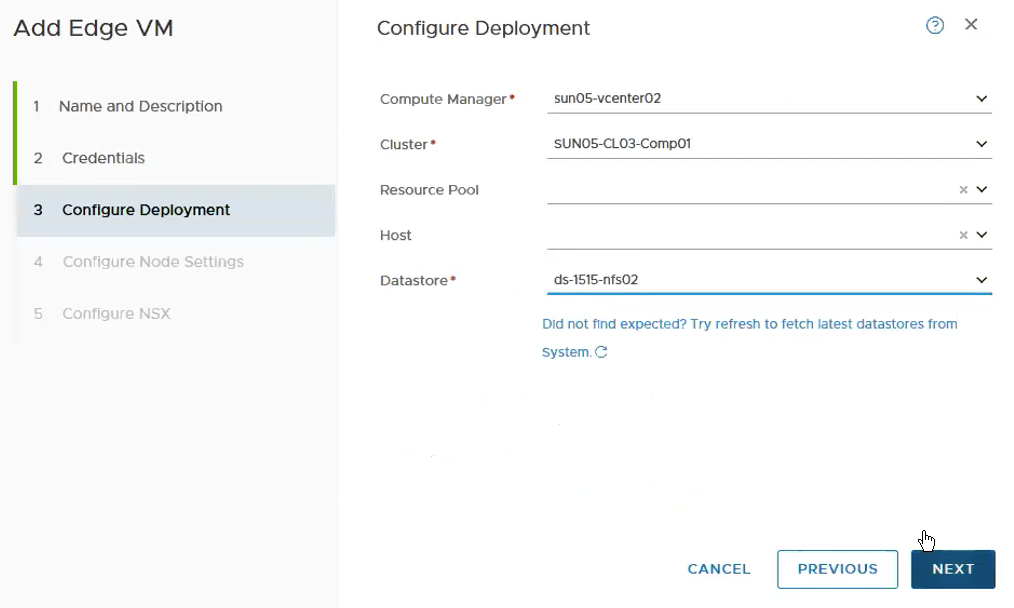
Select the Compute Manager, Cluster and Datastore.
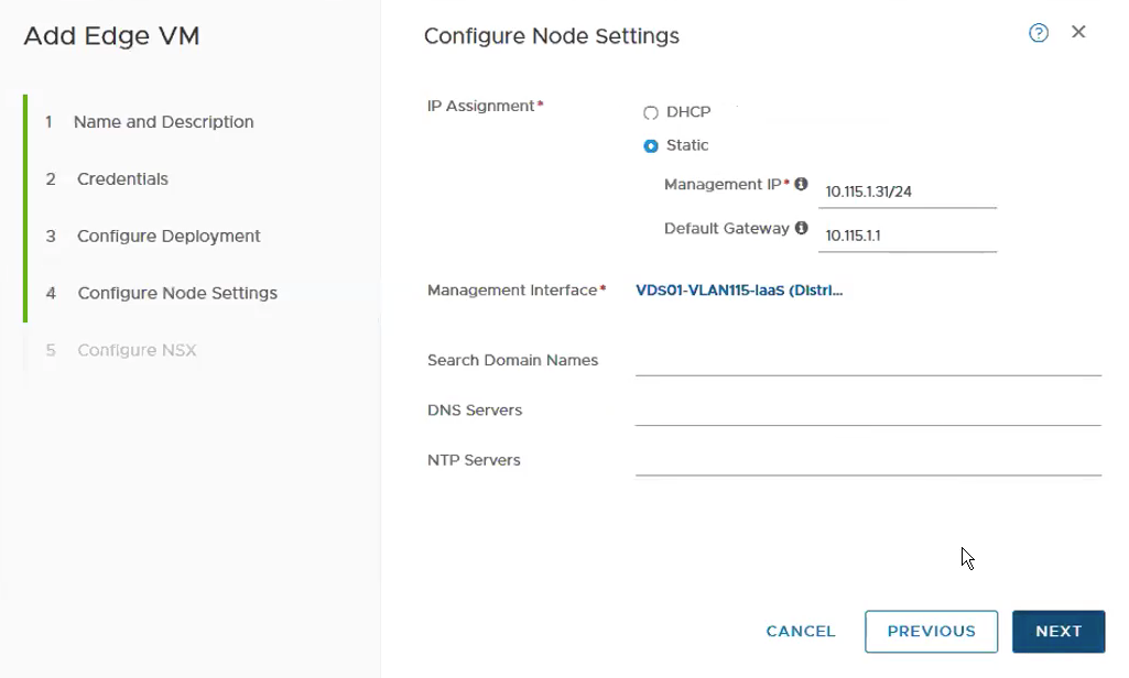
Configure the Management IP and choose the Portgroup for the Management Interface.
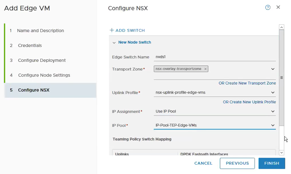
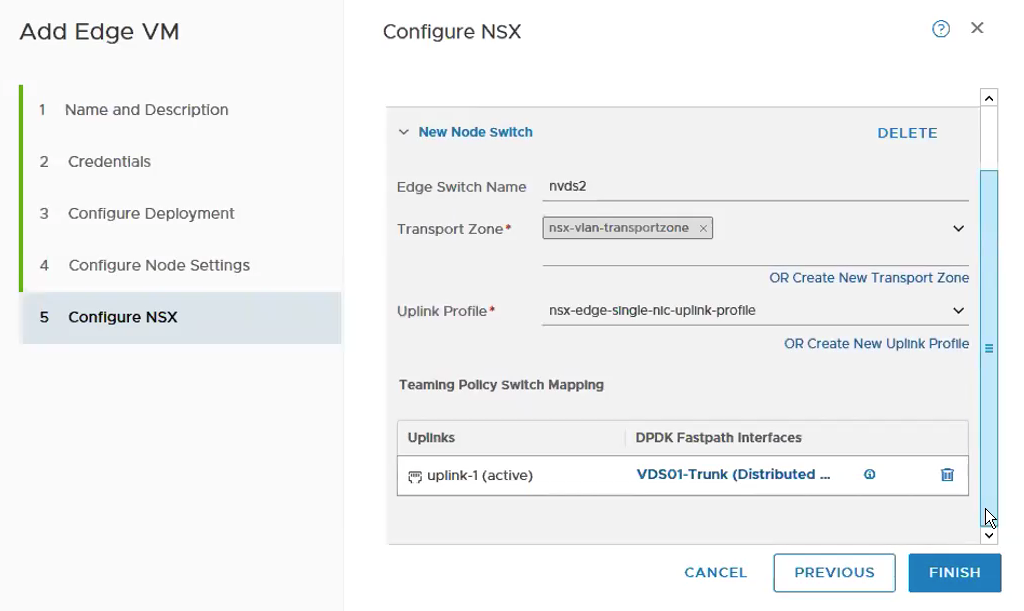
Select the Transport Zone, Uplink Profile, IP Assignment and the IP Pool for the TEPs for the Edge VM. I usually keep the naming convention of nvds1 for overlay and nvds2 for VLAN transport zone.
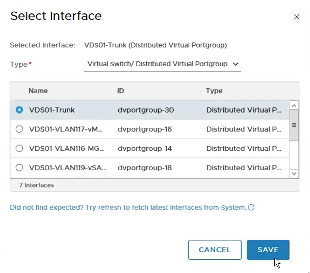
Select the VDS Portgroup – VDS01-Trunk which we created in Step 1.
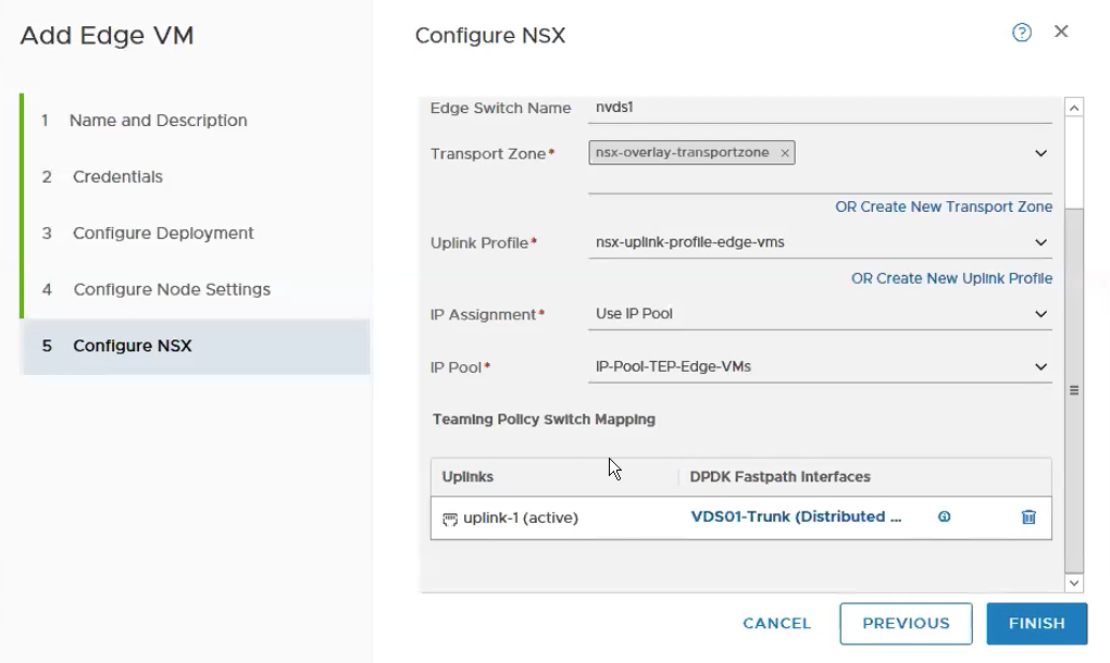
It will look like the following with all the required fields being selected and fill up.
Add another switch by click on ADD SWITCH. **You might need to scroll up to the page to see the button.
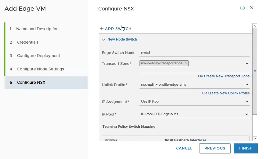
Again, select the Transport Zone, Uplink Profile and the VDS portgroup that would be use for the uplinks. I usually keep the naming convention of nvds1 for overlay and nvds2 for VLAN transport zone.
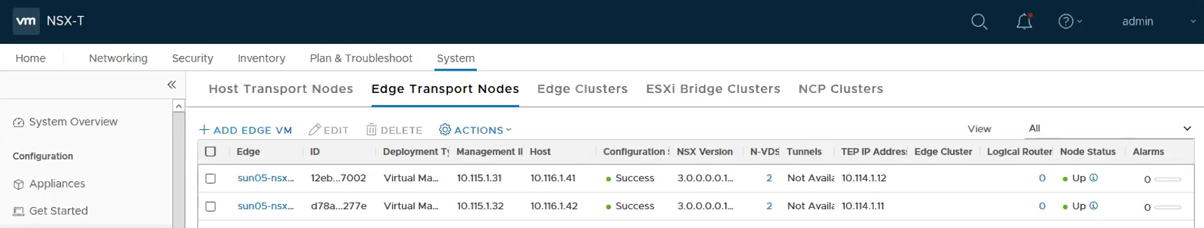
Repeat the above steps for Edge VM02. It will look like the following once both the Edge VMs are deployed successfully.
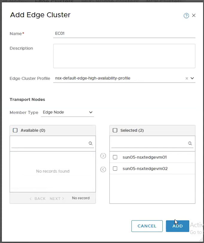
Step 9 – Configure the Edge Cluster
System -> Fabric -> Nodes -> Host Transport Nodes -> ADD. Select the two edge nodes that we have been just created in the previous step.
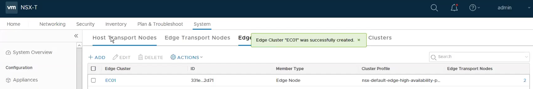
The following shows the Edge Cluster – EC01 has been successfully created.
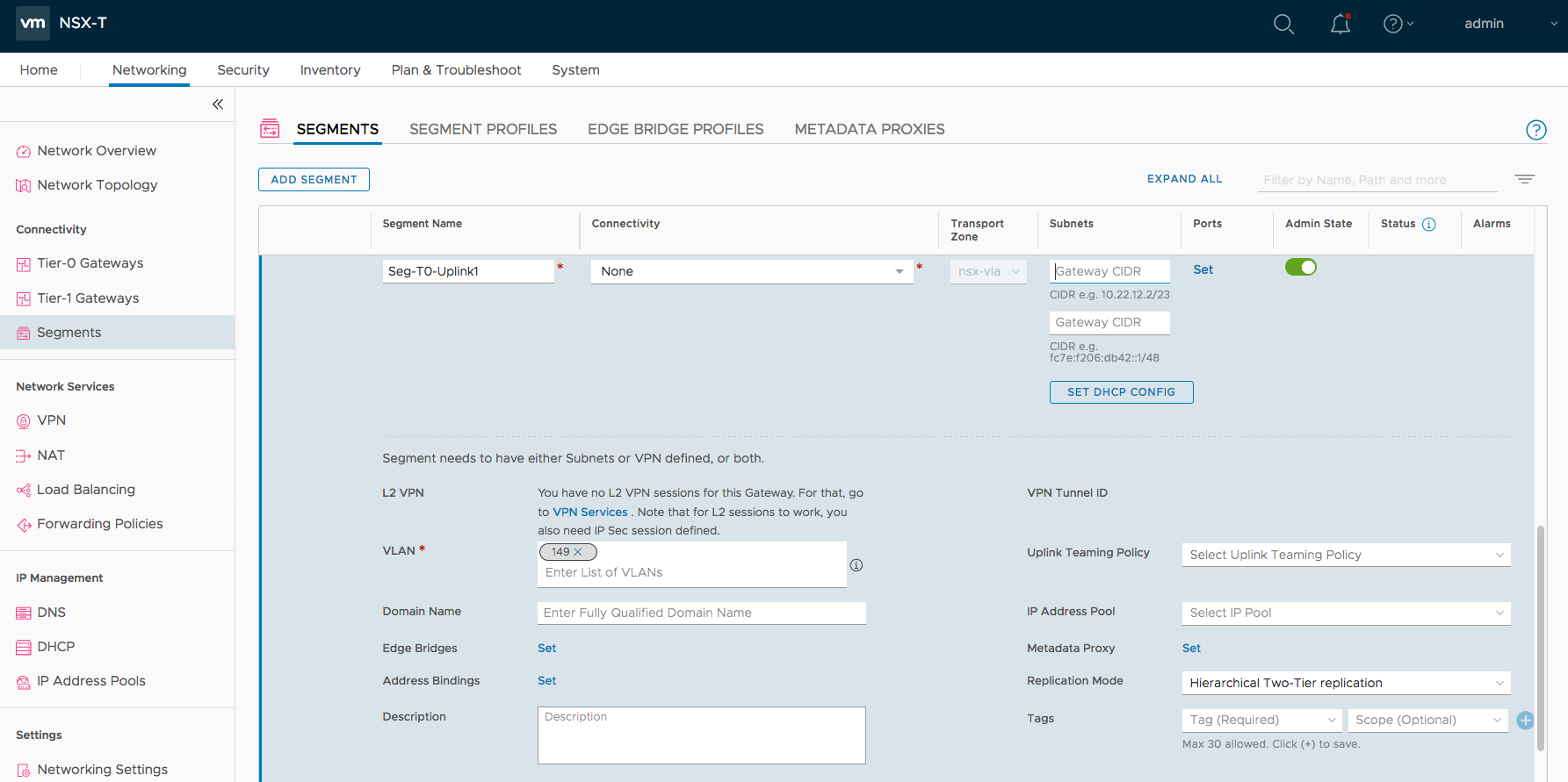
Step 10 – Create the Segment required for Tier-0 Uplinks.
Networking -> Segments -> ADD Segment. Fill up the Segment Name, Transport Zone and Subnets.
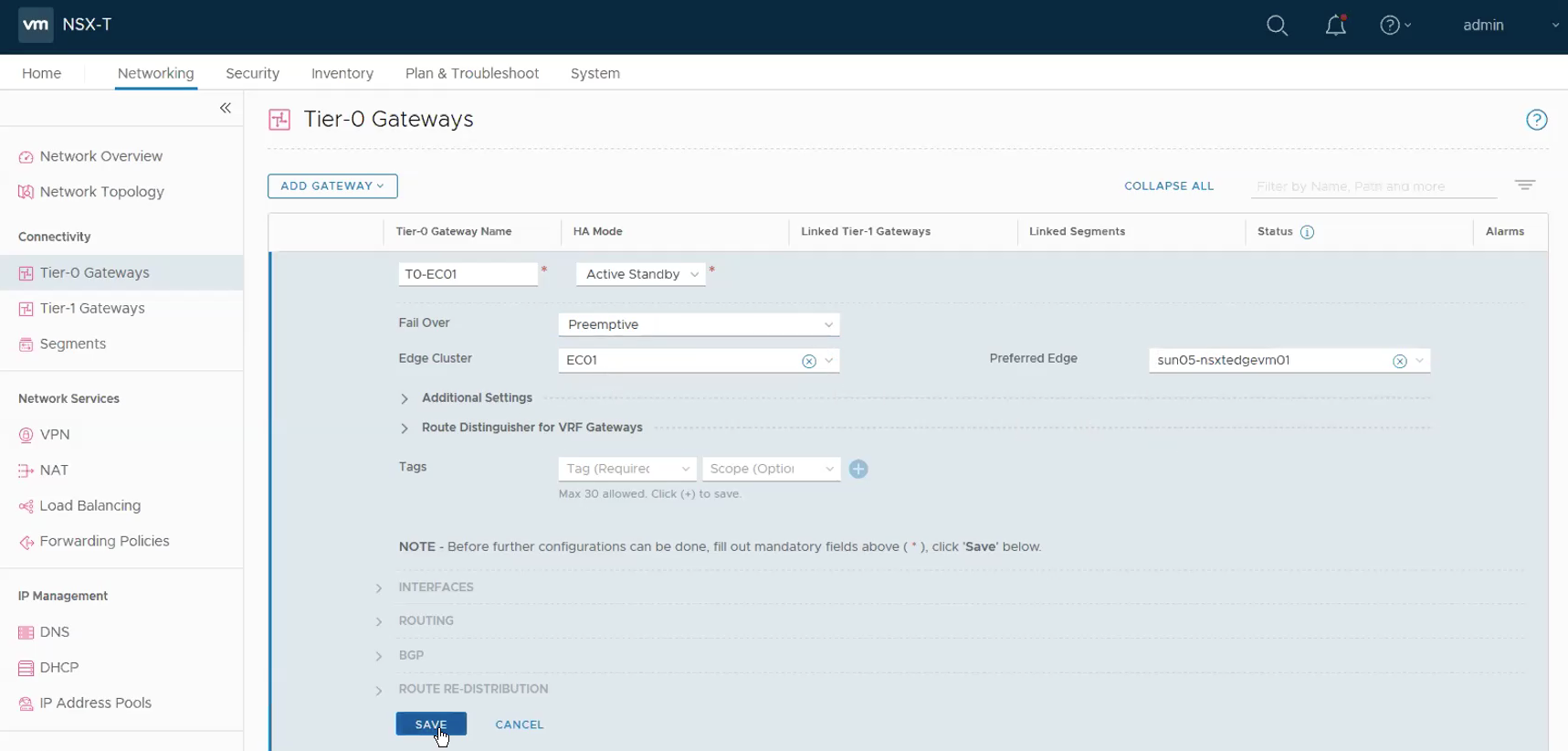
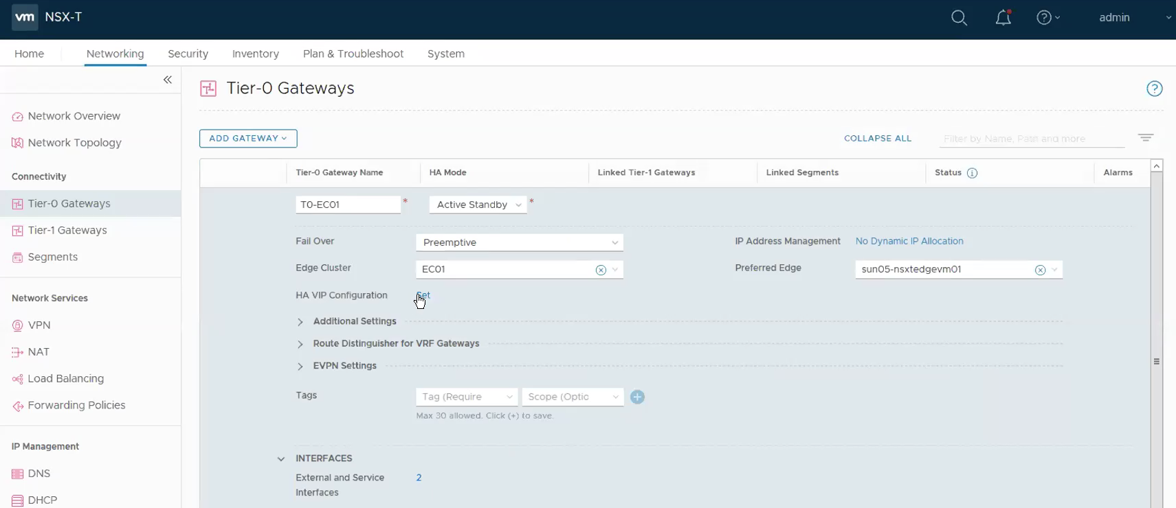
Step 10 – Configure the Tier-0 Gateway.
Networking -> Tier-0 Gateway -> ADD Gateway.
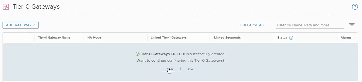
Select Yes when ask whether you wish to continue to configure this Tier-0 Gateway.
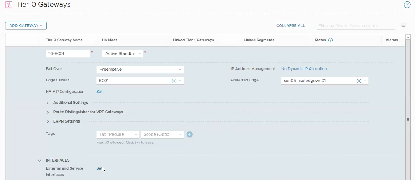
Clik on Set under Interfaces.
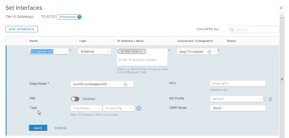
Click on Add Interface.
Name: T0-Uplink1-Int
Type: External
IP Address/Mask: 10.149.1.5⁄24
Connect To(Segment): Seg-T0-Uplink1
Edge Node: sun05-nsxtedgevm01
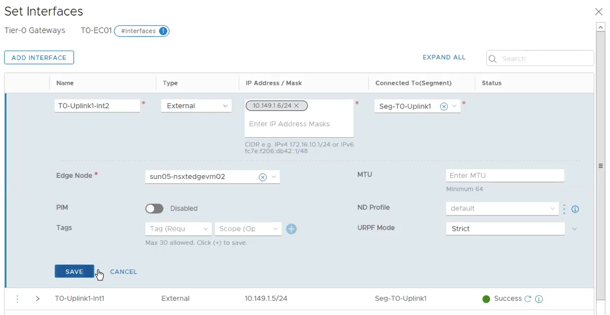
Click on Add Interface for the 2nd Edge VM.
Name: T0-Uplink2-Int
Type: External
IP Address/Mask: 10.149.1.6⁄24
Connect To(Segment): Seg-T0-Uplink1
Edge Node: sun05-nsxtedgevm02
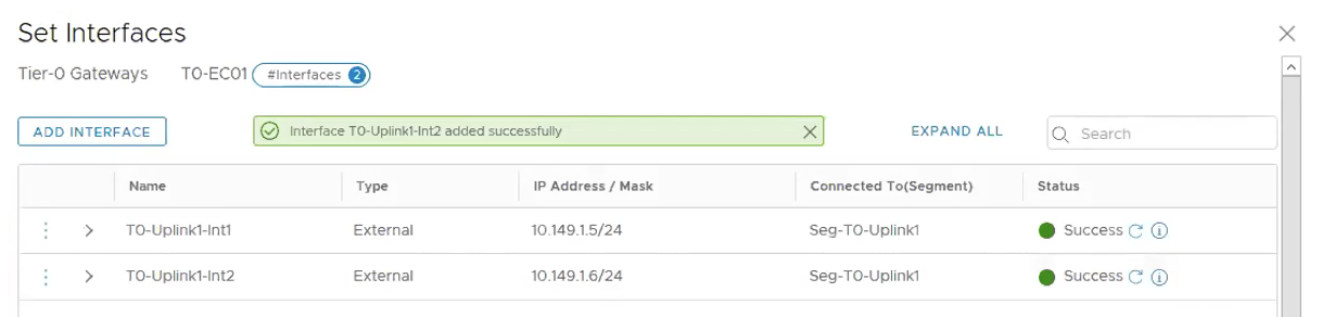
The following shows both interfaces for the Tier-0 Gateway are created correctly.
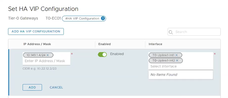
Click on Set under HA VIP Configuration.
Click on **ADD HA VIP CONFIGURATION.
** IP Address / Mask: 10.149.1.4⁄24
Interface: T0-Uplink1-Int1, T0-Uplink1-Int2
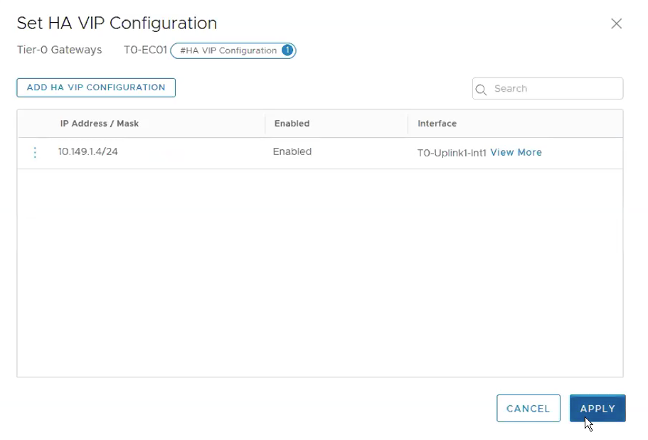
The following shows the HA VIP Configuration has been successfully created.
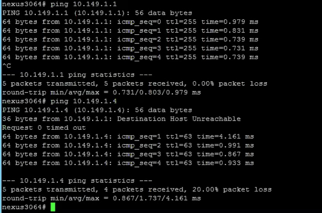
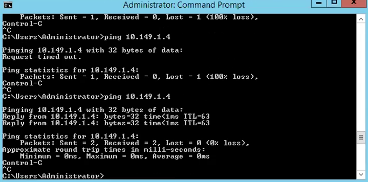
To ensure that the Tier-0 Gateway Uplink is configured correctly, we shall login to the next hop device, in my case is the Nexus 3K, to do a ping test.
I first ping myself ie. 10.149.1.1 which is configured on the switch then follow be the HA VIP configured on the Tier-0 Gateway.
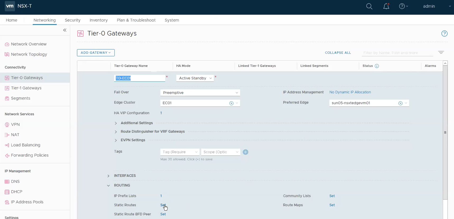
Lastly we need to configured a default route out so that the containers can communicate back to IP addresses outside the NSX-T domain.
Under Routing, Click on Set under Static Routes. **BTW, if you are using BGP, then probably this step would differ.
Click on ADD STATIC ROUTE.
Name: Default
Network: 0.0.0.0/0
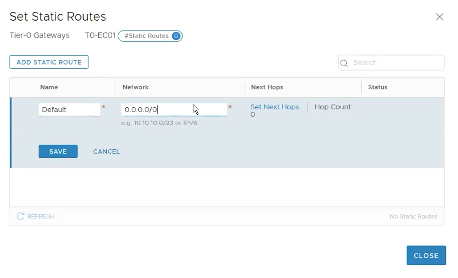
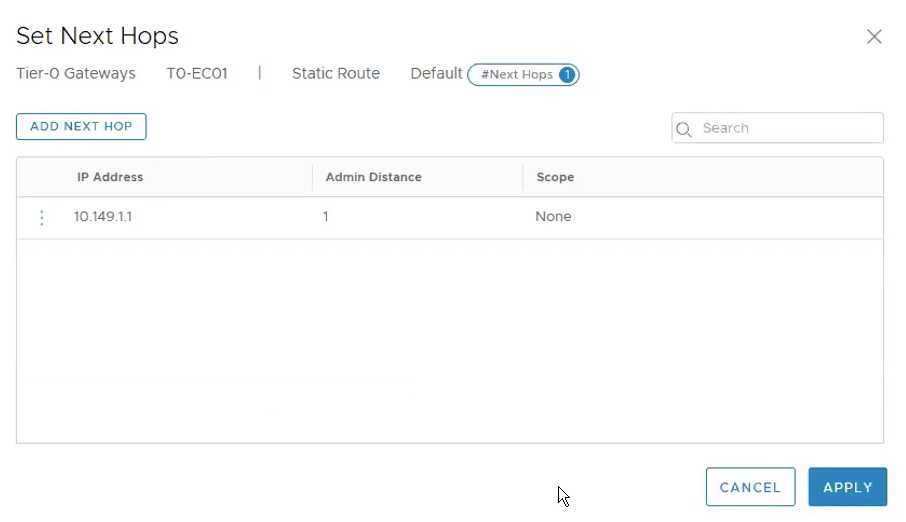
Click on Set Next Hop, ADD NEXT HOP.
IP Address: 10.149.1.1
Once the static route has been added, one way to test is from outside the NSX-T domain. In my case, I have a jumphost which is outside the NSX-T domain and the gateway of the jumphost is pointing to the N3K as well. I did a ping test from the jumphost to the Tier-0 Gateway VIP. If the ping test is successful, it means the static route we added to the Tier-0 gateway is successfully configured.
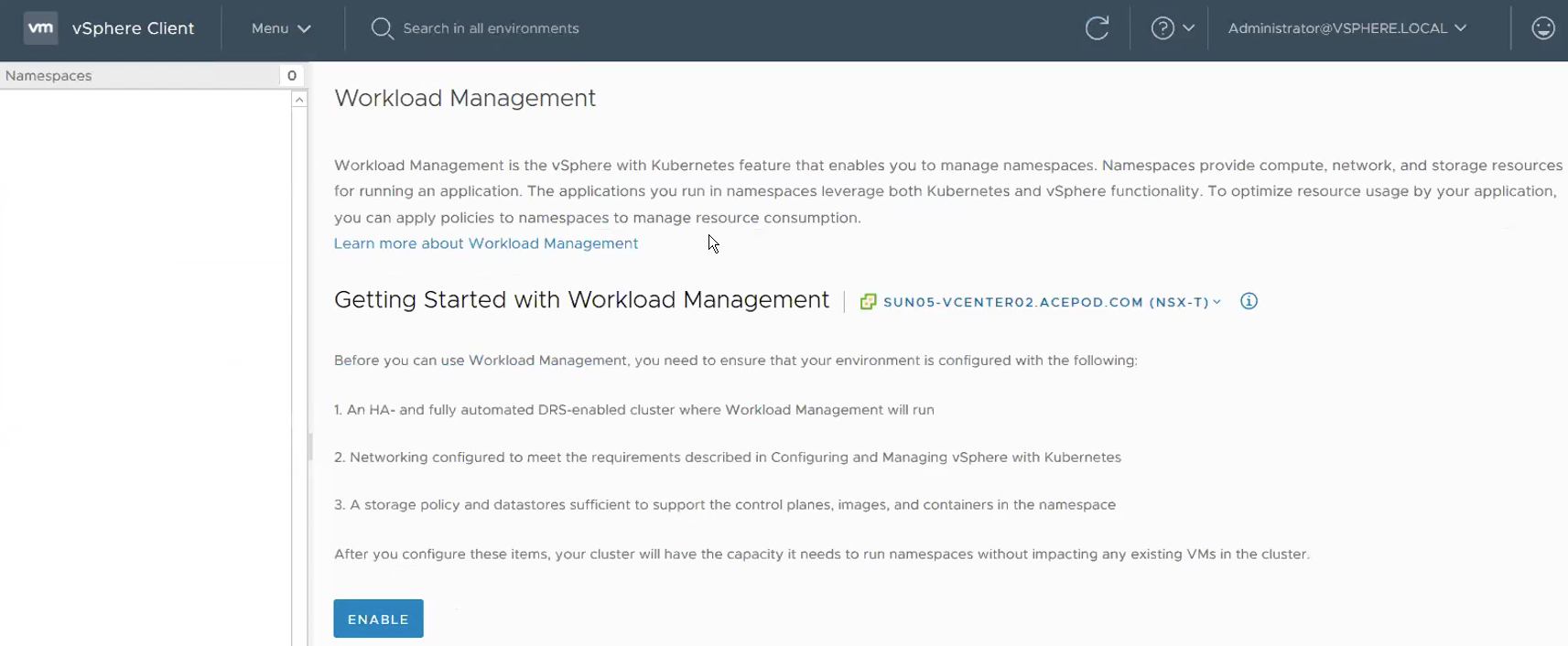
Step 10 – Validate whether NSX-T has been successfully set up for vSphere with Kubernetes.
With all the configuration on the NSX-T, vSphere VDS and physical network are set up, its now to go back to Workload Management to see whether we are ready to deploy Workload Management Clusters! And YES we can! NSX-T is now detected by Workload Management!
Now we are done with NSX-T and related networking configurations. Give yourself a pat here! A lot of the questions related to vSphere with Kubernetes during the Beta whether for customers or internally were due networking and NSX related questions. Next, we will start configuring things required for Workload Management such as storage policies, Content Library, etc, mostly on the vCenter side.
Reference:
Tanzu vSphere 7 with Kubernetes on NSX-T 3.0 VDS Install
Part 1: Overview, Design, Network Topology, Hardware Used
Part 2: ESXi, vCenter, VDS Config and NSX-T Manager
Part 3: NSX-T Edges, Segments, Tier-0 Routing
Part 4: Supervisor Cluster, Content Library, TKG Clusters